

Ever wished to change the pitch after printing the picture?
- Yitzhak Weissman

- May 14, 2019
- 3 min read
I bet that the answer is yes. Continue reading to learn how to do it (Spoiler: it is not practical)
Introduction
All lenticular print practitioners are familiar with lenticular lens sheets. However, there is another well known lens which comes in a sheet format: the Fresnel lens. These lenses greatly differ by their optical characteristics and applications. However, what will happen if we decide to combine them together?
A stack of lenticular and Fresnel lenses has some peculiar optical properties. Here, we will discuss some phenomena which are relevant to lenticular pictures. We will see that a Fresnel lens can be used to modify the lenticular pitch (or the effective viewing distance), and also the viewing angle.
Emulation of infinite-distance viewing with a Fresnel lens
The diagram below shows a stack of lenticular and Fresnel lens sheets with an observer at the focal point of the Fresnel lens. The rays emerging from the observation point are refracted by the Fresnel lens an hit the lenticular lens orthogonally. This emulates an infinite viewing distance. In other words, if the lenticular pitch is adjusted to fit an infinite viewing distance, the stack viewing distance will be the Fresnel lens focal distance.

General viewing distance
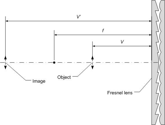
Let us consider now the general case using the diagram in Fig. 2 below. It shows a Fresnel plano-convex lens (the common type) with three objects: the lens, the object, and its image. The distances of the object and its image from the lens surface are denoted by V and V' respectively. These three distances are related by the well known formula
1/V + 1/V' = 1/f Equation 1
where f is the Fresnel lens focal length. In the present case, the "object" represents the observer, and the "image" represents his location as "seen" by the picture.
Both V and V' are signed. If both appear at the same side of the lens, they are of opposite signs. We will regard V as positive, so V' in the diagram is negative. The focal length f is also signed. For a plano-convex lens, like the one shown in the diagram, f is positive.
Suppose that the lenticular picture has a calibrated viewing distance of V*. To calculate the viewing distance V with the Fresnel lens, one has to substitute -V* for V' in Equation 1. The result is
V = fV*/(f + V*)
The new viewing distance V is smaller from both f and V*. In particular, if V* = inf, then V = f.
Lenticular pitch change illustration
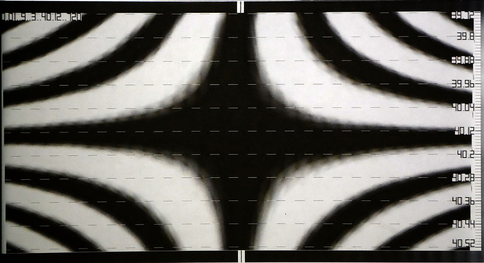
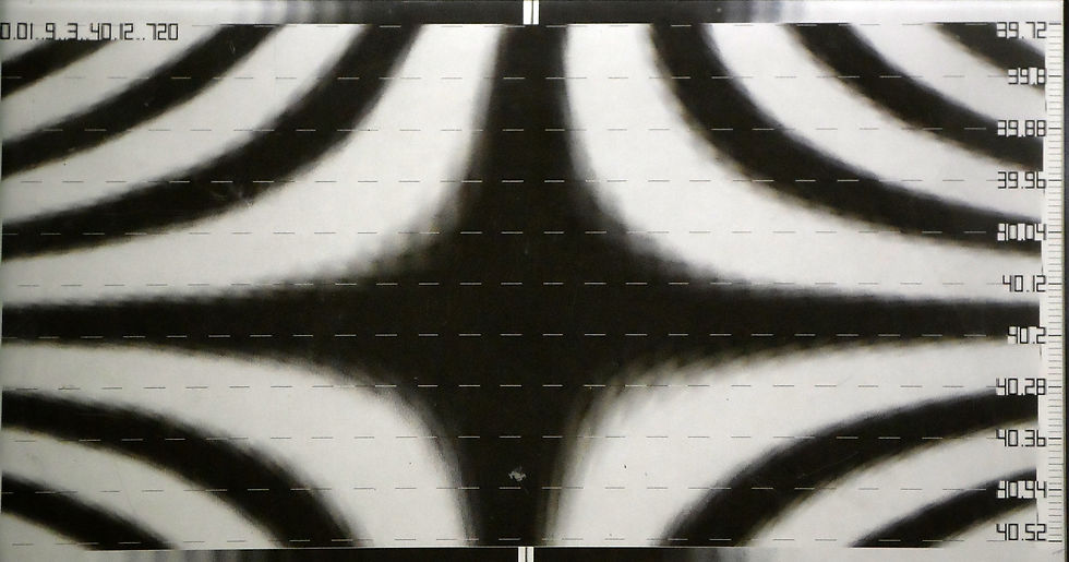
The effect of a Fresnel lens on the lenticular pitch is illustrated below with an Fpitch calibration pattern. Fig. 3 shows an Fpitch calibration pattern of a 40lpi lens photographed from 1000mm distance. Fig 4 shows a photograph of the same pattern taken from the same distance, but this time with a Fresnel covering it. The focal length of the Fresnel lens was 1000mm, so this picture shows how the pattern would have been seen if observed from infinity.
The difference between the pitch values in the two pictures is approximately 0.05/inch. This is in excellent agreement with the theoretical estimate for lens thickness of 2mm, and index of refraction of 1.58.
The effect on the viewing angle
In Fig. 1 it was assumed that the observer is located on the central normal of the Fresnel lens. Fig. 5 below shows what happens when the observer is laterally shifted. In this case, the rays that are incident on the lenticular create a finite angle with respect to the normal. This introduces a non-zero viewing angle, even though the observer may be still on the central normal of the lenticular picture. Therefore, moving the Fresnel lens (in the direction perpendicular to the lenticules) will animate the lenticular picture even if both the observer and the picture are static.

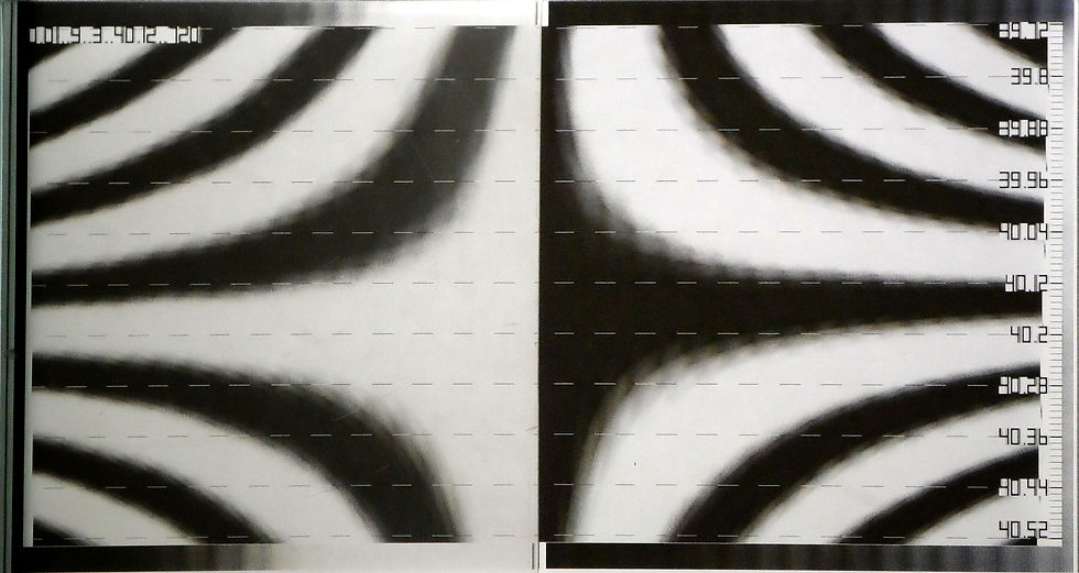
The effect of the decentering on the viewing angle can be also illustrated with the Fpitch pattern. Fig. 6 below is the same as Fig. 4 except that only the left half of the pattern was covered by the Fresnel lens. The center of the Fresnel lens is located on the left edge of the pattern, and its right edge crosses the pattern in the middle. The viewing angle modification is manifested by the clearly visible shift of the pattern display.


Comments